Python出图御用模块。
# 序
提高 matplotlib 绘图能力是解决数据处理、数据分析可视化困境的有效途径,掌握 matplotlib 的运用技巧更有助于提升数据分析的直观程度,因此开贴记录 matplotlib 的相关使用方式是必要的。
参考极客鸭geekDuckKonig的视频讲解。
# 入门实例
pyplot.plot() 第一个第二个传入的量分别是X坐标与Y坐标,第三个传入的量为线段和点的样式。样式可以参照官方文档,三个字符分别指定 颜色/点的样式/线的样式 。from matplotlib import pyplot
# 创建数据
x_list = [1, 2, 3, 4]
y1_list = [2, 4, 6, 6]
y2_list = [8, 8, 3, 5]
# 画两条折线
pyplot.plot(x_list, y1_list, 'ro--', label='y1_label')
pyplot.plot(x_list, y2_list, 'b^--', label='y2_label')
pyplot.plot(x_list, y2_list, color='green', marker='o', linestyle='dashed',
linewidth=2, markersize=12 label='y3_label')
# 添加标题
pyplot.title('start_up instance')
# 标注X轴与Y轴
pyplot.xlabel('label X-axis')
pyplot.ylabel('label Y-axis')
# 显示图例
pyplot.legend()
# 展示!
pyplot.show()
- .plot(x, y) :折线图
- .scatter(x, y) :散点图
- .bar(x, height)/.barh(y, width) :柱状图
- .stem(x, y) :火柴图
- .step(x, y) :分段折线图
- .fill_between(x, y1, y2) :填充图
具体参照下面的🔗
# 图像的构成
由 matplotlib 输出的图像通常有三个组成部分,分别是数轴/坐标系 Axis/Axes 、整幅输出画面 Figure 与画面中所有可以看到的东西 Artist ——如标题、图示、每个点、每条线等。

from matplotlib import pyplot


# 导入数据
x_list = [1, 2, 3, 4]
y1_list = [2, 4, 5, 2]
# 以面向对象的方式创建figure和axes,figure的横向的长度为9英寸,纵向的长度为6英寸。并指定图像摆放为两行一列。
# 然后返回一个fig和数组axes。后者用于对每一个图像进行操作。
# 因为只有一列,所以只能指定行数来确定操作哪个位置的图像。
fig, axes = pyplot.subplots(2, 1, figsize=(9, 6))
axes[0].plot(x_list, y1_list)
axes[1].scatter(x_list, y1_list)
# 展示!
pyplot.show()

# 两行三列
fig, axes = pyplot.subplots(2, 3, figsize=(9, 6))
axes[0, 0].plot(x_list, y1_list)
axes[1, 0].scatter(x_list, y1_list)
# 对于不适用的axes可以进行删除
axes[2, 1].remove()
# 设定Figure的总标题与总X/Y轴标签
fig.suptitle('SupTitle')
fig.supxlabel('SupXLabel')
fig.supylabel('SupYLabel')
# 使内容紧凑,功能类似于QGIS的crop to content
pyplot.tight_layout()
# 展示!
pyplot.show()
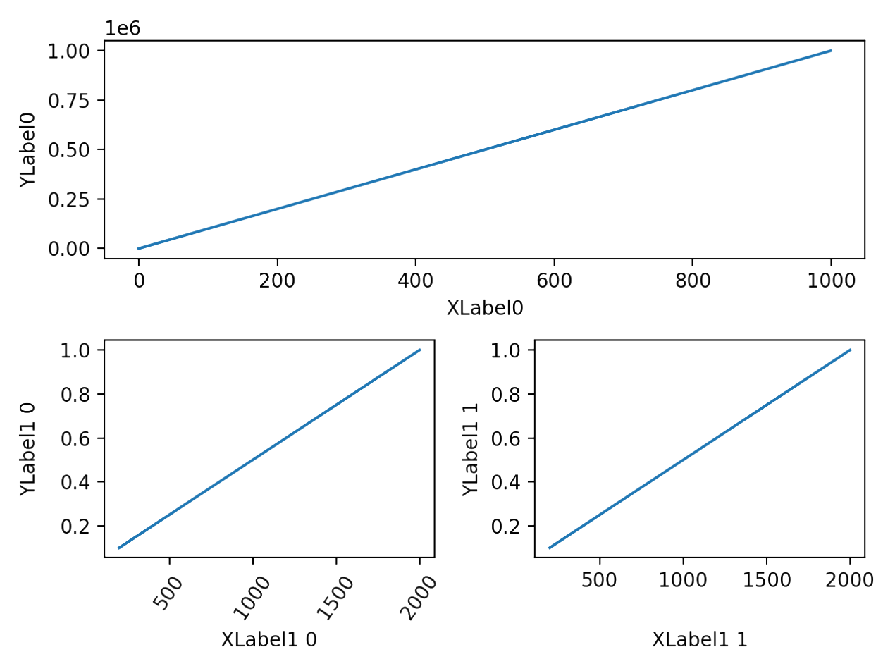
# 不规律布局
使用 .add_gridspec() 以对坐标系进行复杂布局。与上面创建规则布局略有不同,以下为创建不规则布局的流程。不难发现,之前使用 .subplots() 一次初始化了fig和axes,而现在是先初始化fig,再在fig上添加axis。
from matplotlib import pyplot
from matplotlib import gridspec

# 初始化Figure
fig = pyplot.figure()
# 初始化GridSpec,如下共分配两行两列的空间
gs = gridspec.GridSpec(2, 2)
# 新建一个坐标系,占用第一行的两列空间
ax1 = fig.add_subplot(gs[0, :])
# 新建两个坐标系,分别占用第二行第一列的空间和第二行第二列的空间
ax2 = fig.add_subplot(gs[1, 0])
ax3 = fig.add_subplot(gs[1, 1])
# 接下来通过操作ax来完善这三幅图表
# 工作流
使用 matplotlib 绘图基本流程为——导入模块、设置风格、
# step1 导入模块
from matplotlib import pyplot
import matplotlib
# step2 设置绘图风格
pyplot.style.use('ggplot') # 更多风格参见https://matplotlib.org/stable/gallery/style_sheets/style_sheets_reference.html
# 保存图片,设置透明背景与DPI
pyplot.savefig('img.png', transparent=True, dpi=300)
# step3 设置全局参数,如字体、DPI等
# 设置支持中文的字体,不推荐,下文将给出使用中文的例子。
matplotlib.rcParams['font.family'] = ['SimSun']  # MacOS使用Songti SC
# 设置全局DPI
matplotlib.rcParams['figure.dpi'] = 300
# 打印数学公式,以下代码需要额外安装LaTex,不推荐。实际上matplotlib内置了tex,因此不需要设置也能以tex的方式输入数学公式如r'$t=1$'
matplotlib.rcParams['text.usetex'] = True
# Figure自动调整格式
matplotlib.rcParams['figure.constrained_layout.use'] = True
# 补充:像上面这样一条一条更新参数看起来不美观,可以用字典来统一更新
rc = {'axes.facecolor':'red', 'savefig.facecolor':'yellow', 'font.family':'Heiti SC'}
matplotlib.rcParams.update(rc)
# step4 进行绘图
...
# step5 优化细节
# 把第一个坐标系的X轴标签删掉
axes[0].set_xlabel('')
# 显示(或调整)第二个坐标系的图例(的位置)
axes[1].legend(loc='upper right')
# 增加第三个坐标系的网格线
axes[2].grid()
# 重新设置第四个坐标系的第一条线的标签,以便于展示出它的图例
axes[3].lines[0].set_label('New Label')
axes[3].legend(loc='lower left')
# step6 展示!
pyplot.show()
上述代码需要注意的是,与入门实例部分的代码不同,这里通过操作 axes 来绘图,因此使用的方法不尽相同。如使用 axes 给某一特定坐标系添加(更新)标记、X/Y轴范围等,应使用正确的方法,譬如 axes[0].set_xlim() 。
有一个特殊的情况是,既要输出中文又要输出数学公式。此时主字体应设置为英文字体,并设置数学公式字符集,在使用中文的部分指定 fontname 为中文字体。具体如下所示。需要注意的是,公式 $ 内等号后使用中文会导致该部分乱码。
rc = {'font.family': 'Times New Roman', 'mathtext.fontset': 'stix'}
matplotlib.rcParams.update(rc)
...
axes[0].set_xlabel('密度$\mathrm{kg/m}^3$', fontname='Heiti TC', fontsize=20)
建议通过指定 fontproperties 来使用中文,这样不用更改全局字体,用中文的时候再指定。若公式与中文并存,参考上一段文字。
ax.set_title('中文测试', fontproperties='SimSun')
# 使用以下代码查找计算机中有哪些字体
print(matplotlib.font_manager.get_font_names())
# pyplot.subplots()
在使用该函数初始化fig和axes时可以设定它们初始化参数。
# 仅创建一个坐标系
fig, ax = pyplot.subplots(figsize=(5, 5), dpi=120)
# 设定初始化fig的大小、分辨率、背景颜色、边缘颜色等
fig, axes = pyplot.subplots(2, 3, figsize=(9, 6), dpi=300, facecolor='red', edgecolor='yellow')
# 设定初始化axes的是否公用xy轴、坐标系种类等。以及一些其他样式,如每行的高度之比,每列的宽度之比之类的。
fig, axes = pyplot.subplots(2, 3, figsize=(9, 6), sharex='col', sharey='all', subplot_kw=dict(projection='polar'), gridspec_kw=dict(height_ratios=[1, 3]))
# pyplot.subplots_adjust()
调整每个子图的基本属性。
更改横向、纵向子图之间的间距
w means width, and h represents height.
pyplot.subplots_adjust(wspace=.1, hspace=.3)
# 后端交互
开发软件时可能用到,可以进行交互或仅返回图像。一旦绘图之前设定完成,则不要进行反复切换。
Matplotlib Backends
相关代码如下所示:
# 显示处理
pyplot.show() # 显示当前figure
pyplot.close() # 关闭当前figure
pyplot.get_fignums() # 查询当前所有图像编号
# 删除元素
pyplot.clf() # clear the current figure
pyplot.cla() # clear the current axes
pyplot.close('all') # close all the figure windows
# Links
下述链接将有助于 matplotlib 的自主学习:
- https://www.python-graph-gallery.com/
- https://matplotlib.org/stable/gallery/index.html
接下来将记录实际使用 matplotlib 出图过程中遇到并解决的问题及相关代码实例。
# 折线图上添加数值文本信息
在 matplotlib 中绘画折线使用 .plot() ,其 label= 参数主要作用是为这条线添加标签。所以,若想在折线上添加数值文本信息,需要使用 .text() 。
years_list = [1953, 1964, 1982, 1990, 2000, 2010, 2020]
props_list = [7.32, 6.13, 7.62, 8.57, 10.33, 13.26, 18.7]
# ax1为之前创建的坐标轴
for x, y in zip(years_list, props_list):
    ax1.text(x, y+1, str(y)+'%', horizontalalignment='center', verticalalignment='center')
# 在已有图中增添小图
或许前几年实现“图中图”较为复杂,但新版本增添的 Axes.inset_axes() 降低了其实现难度。
# 在ax1中添加ax2,前两个参数控制ax2相对于ax1的位置,后两个参数控制坐标系大小
ax2 = ax1.inset_axes([-0.05, 0.4, 0.6, 0.6])
# 绘画甜甜圈饼图
通过调整 .pie() 函数中的 wedgeprops= 参数便可实现甜甜圈饼图的绘制,该参数实际上可以调整每块扇形的宽度、边缘颜色等。
ax2.pie(size_of_7th, labels=['17.95%\nunder 15', '63.35%\n15 ~ 60', '18.70%\nover 60'], wedgeprops=dict(width=0.3, edgecolor='w'))
方法 .pie() 中有个名为autopct的参数,既可以跟字符串格式化函数,也可以跟其他函数。其中,字符串格式化函数 fmt 的基础用法如下:
ax.pie([num_list], colors=color_pie_list, autopct='%.1f%%', textprops=dict(color='w'))

fmt中'%.1f'为保留一个小数,%%为输出百分号。
# 为折线图添加竖(横)线指向数据点
有多种方式为 Axis 添加竖(横)线,这里介绍其中两种。
使用 .vlines(x, ymin, ymax,…, **kwargs) 能为坐标轴添加确定长度的竖线,该函数中 ymin/ymax 为确切长度(坐标轴刻度)。而 .axvline(x, ymin, ymax, **kwargs) 中的 ymin/ymax 为ylim的相对位置,其大小在0到1之间。
fig, ax = pyplot.subplots(figsize=(5, 5), dpi=120)

# 在x=1处,添加一条长为0.5的竖线
ax.vlines(x=1, ymin=0, ymax=.5)
# 在x=1处,添加一条长为ylim一半的竖线
ax.axvline(x=1, ymin=0, ymax=.5)
# 给标签加框框
本想给饼图的每个label加一个外框,尝试了多种方法均以失败告终。最终只能使用 .text() 手动添加Artist来装成label。代码中的 bbox= 便是设置外框的参数。
ax1.text(-1.3, -0.3, '15~60', color='red', alpha=.6, va='center', ha='center', style='italic', weight='heavy',
         bbox=dict(boxstyle='round,pad=0.3', fc='yellow', lw=2, alpha=.7))
实际上 bbox 也可以直接用来给坐标轴的标题、轴标签等添加样式。
# 以标题举例
ax1_title = ax1.set_title('不同年龄段人群数量占比', fontname='simsun')
ax1_title.set_bbox(dict(boxstyle='round,pad=0.3', fc='#E2E2E2', lw=2, alpha=.7))
# 截断坐标轴
当数据与数据之间差距太大又想放在同一个坐标轴时就需要截断坐标轴,然而实际上需要创建一列两个或多个子图来实现截断坐标轴的效果。
# 定义数据
walk_means = numpy.array([1200, 1203, 1234])
ride_means = numpy.array([400, 410, 420])
bus_means = numpy.array([1200, 1240, 1050])
drive_means = numpy.array([340, 350, 360])
# 定义X的数据与X轴标签
x = numpy.array([1, 2, 3])
labels = numpy.array(['Morning', 'Afternoon', 'Evening'])
# 初始化,为了做出截断效果,需要用subplots_adjust()来调整它们之间的距离,这里的hspace是height space
fig, ax = pyplot.subplots(2, 1, figsize=(5, 5), dpi=120, sharex=False)
fig.subplots_adjust(hspace=0.1)
# 设置X轴
ax[1].set_xticks(x, labels, rotation=45)
# 画折线
ax[0].plot(x, walk_means, 'ro--', label='Walk means')
ax[0].plot(x, bus_means, 'yo--', label='Bus means')
ax[1].plot(x, ride_means, 'go--', label='Ride means')
ax[1].plot(x, drive_means, 'bo--', label='Drive means')
# 定义两段ylim
ax[0].set_ylim(1150, 1400)
ax[1].set_ylim(350, 450)
# 隐藏不需要的部分
ax[0].spines.bottom.set_visible(False) # 隐藏上图的底框
ax[1].spines.top.set_visible(False) # 隐藏下图的顶框
ax[0].tick_params(axis='x', length=0, labelbottom=False) # 隐藏X轴的标签,并把刻度(小短线)的长度设为0
ax[0].grid()
# 截断线
kwargs = dict(marker=[(-1, -.5), (1, .5)], markersize=12,
              linestyle="none", color='k', mec='k', mew=1, clip_on=False)
ax[0].plot([0, 1], [0, 0], transform=ax[0].transAxes, **kwargs) # 给上图的左下角和右下角画(-1, -0.5)与(1, 0.5)俩坐标组成的短线。transform实际上
ax[1].plot([0, 1], [1, 1], transform=ax[1].transAxes, **kwargs)
pyplot.legend(loc='upper right')
pyplot.show()
补充一些知识点:
使用 Axis.spines 可以操作子图的上下左右边框。
matplotlib 有四种坐标系:- 用户空间数据坐标系统:由数据的(x, y)决定位置
- Axes坐标系:0~1,坐标轴的相对位置。如(0, 0)为左下角,(1, 0)为右下角
- Figure坐标系:0~1,Figure的相对位置
- Display坐标系:显示窗口的Pixel坐标系,(0, 0)为窗口的左下角,(width, height)为窗口右上角。这是绝对数,包括对象在水平和垂直方向上的尺寸也是绝对值,但是以 pixels 为单位。对象的物理尺寸(以 inches 为单位)还与 dpi 有关。
下表总结了 matplotlib 绘图常用的坐标系:数据来源于博客。
 Coordinates	     Transformation object	       Description
    Data	          ax.transData	       Data 坐标系,由 xlim 和 ylim 控制。
    Axes	          ax.transAxes	       Axes坐标系,(0, 0) 是 axes 的左下角, (1, 1) 是 axes 的右上角
   Figure	        fig.transFigure	       Figure坐标系, (0, 0) 是 figure 的左下角, (1, 1) 是 figure 的右上角。这是相对数,包括对象在水平和垂直方向上的尺寸也是相对于 Figure 的宽和高的。
 Figure-inches	  fig.dpi_scale_trans       Figure 以 inches 为单位; (0, 0) 是 figure 的左下角, (width, height) 是 figure 的右上角。这是绝对数,包括对象在水平和垂直方向上的尺寸也是绝对值,以 inches 为单位。
   Display	   None或 IdentityTransform()      显示窗口的 pixel 坐标系统;(0, 0) 是显示窗口的左下角, (width, height) 是显示窗口的右上角,以 pixels 为单位。这是绝对数,包括对象在水平和垂直方向上的尺寸也是绝对值,但是以 pixels 为单位。对象的物理尺寸(以 inches 为单位)还与 dpi 有关
Xaxis, Yaxis         上述Object选两个	       混合坐标系;在一个 axis 上使用 data 坐标,在另一个上使用 axes 坐标系。
其中一种方法是像上述代码一样,将小物件用 kwargs 的方式传进去。另一种方法如下:
# 新建要添加的小物件,设置好变换坐标系。比如一个圆,半径为xlim的0.1倍,圆心位于Axis的左上角。
circle = patches.Circle((0, 1), radius=0.1, transform=ax.transAxes)
# 通过add_artist()方法加进坐标系
ax.add_artist(circle)

# 上述实例若想使用混合坐标系,则应这样写
trans = transforms.blended_transform_factory(x_transform=ax.transData, y_transform=ax.transAxes)
circle = patches.Circle((0, 1), radius=0.1, transform=trans)
ax.add_artist(circle)
# 更换图例顺序
自动添加图例时若顺序不正确则看起来显得不顺眼,下述代码实现手动调整图例顺序。
# 分别把第2个、第1个、第3个图例放在第1位、第2位和第3位
legend_handles, legend_labels = ax3.get_legend_handles_labels()
legend_order = [1, 0, 2]
ax3.legend([legend_handles[idx] for idx in legend_order], [legend_labels[idx] for idx in legend_order], loc='upper right')
# 输出横向图例
最简单的方法是设置 ncol= 参数以实现横向放置图例的目的。其中, mode= 参数控制图例要素的宽幅,当设置为expand时图例将与该坐标轴等宽。
# 设置ncol=图例的个数
ax.legend(ncol=5, mode='expand', loc=(0, 1.01))
# 手动添加图例
使用 for loop 绘制一段折线时,调用 legend() 方法添加图例会重复增添与循环次数相符的图例。
此时应清除绘制函数中的 label 参数,并考虑手动添加图例,具体代码如下:
legend_elements = [patches.Rectangle(xy=(0, 0), color='#ac4425', width=1, height=1, label='Extremely Low'),
                   lines.Line2D([0, 0], [0, 0], color='red', label='line1'),
                   lines.Line2D([0], [0], label='point', marker='^', color='black', linestyle='') # 点
                   ]
axes[0].legend(handles=legend_elements)
若自定义图例元素的标签含中文,则需要在 .legend() 中做出如下更改:
axes[0].legend(handles=legend_elements, prop=dict(family='SimSun'))
去除图例的边框:
axes[0].legend(handles=legend_elements, frameon=False)# 分组条形图
看起来像分了组的诀窍是给不同组别之间设定点间隙,而同一组不设置间隙。
# 每条bar的宽度
width = .3
multiplier = 0
# 三个组
group_name = ('alpha', 'beta', 'gamma')
# 两笔数据
vals_three_groups = {
    'data1': [1, 2, 3],
    'data2': [4, 5, 6]
}
x_list = numpy.array([1, 2, 3])
fig, ax = pyplot.subplots()
for attr, val in vals_three_groups.items():
    # 设定偏移量,第一次画第一笔数据,应该是没有偏移的。第二次就偏移了一倍width,所以刚好挨着
    offset = width * multiplier
    rects = ax.bar(x_list + offset, val, width, label=attr)
    # 使用fmt来设置小数点位数,值还可以为'%.3f'
    ax.bar_label(rects, fmt='{:.3f}', padding=3, fontsize=6, label_type='center')
    # 一边画第二组数据时整体偏移
    multiplier += 1
# 因为第一笔数据从1开始画的,导致第二笔从1+width开始画。若想tick在每组的正中间,则需要调整位置。
ax.set_xticks(x_list + width / 2, group_name, fontsize=10, ha='center', va='center')
# 点缀
如果成图之后感觉还缺点什么,那么 Axes.add_artist() 函数可以把缺失的东西补上去。
from matplotlib import text
from matplotlib import patches
# 补个文字
some_words = text.Text(x=0, y=0, text='text', transform=, bbox=)
ax.add_artist(some_words)

# 添加一个矩形方框
rect1 = patches.Rectangle((-0.0198, -0.025), 0.7788, 0.4482, fill=False, color='pink', linewidth=3, linestyle='--', label='Distribution')
ax.add_patch(rect1)
ax.add_artist(rect1) # 或这个
# 注意画图函数返回的实例和传入画图函数的参数
用上面的方法点缀是不得已而为之,实际上调用画图函数会返回部分实例,可以通过操作这些实例来进行点缀。可以看到 .set() 方法可以更改已有实例的参数,加个外框更改字体之类的(详见此处)。另一种方式是画图时把参数传进去。
# 比如画一张饼图,然后更改其label的样式
pie_patches, pie_texts = ax.pie()
pie_texts[0].set(bbox=dict(boxstyle='round,pad=0.3', fc='w', lw=.5, alpha=.7))
# 修改某个label的位置与另一个label处于一条直线
pie_text_5_pos = list(pie_texts[0].get_position())
pie_text_5_pos[0] = pie_text_5_pos[0] - .4
pie_text_5_pos = tuple(pie_text_5_pos)
pie_texts[5].set(position=pie_text_5_pos)

# 在画图时更改标签样式
ax.pie(list, labels=[], labeldistance=.7, textprops=dict(bbox=dict(boxstyle='round,pad=0.3', fc='w', lw=.5, alpha=.7), ha='center'))
# 弦图
记录一下如何使用 holoviews 绘出一张漂亮的弦图,尽管这和 matplotlib 关系不大。
import pandas
import holoviews
from holoviews import opts, dim
from bokeh.plotting import show

holoviews.extension('bokeh')
holoviews.output(size=300)
df = pandas.DataFrame({
    'from': ['China', 'Italy', 'France', 'USA', 'UK', 'Greenland'],
    'to': ['Greece', 'China', 'Finland', 'Austria', 'USA', 'France'],
    'count': [18, 12, 48, 24, 57, 17]
})
chord = holoviews.Chord(df)
chord_opts = opts.Chord(cmap='Category20', edge_cmap='Category20', edge_color=dim('from').str(),
                        labels='index', node_color=dim('index').str(), title='航班')
show(holoviews.render(holoviews.Chord(chord).opts(chord_opts)))
# 保留小数位数
为坐标轴保留两位小数
from matplotlib import ticker
ax.yaxis.set_major_formatter(ticker.FormatStrFormatter('%.2f'))
为Container保留两位小数
可以修改 fmt= 参数以为其保留小数位数。
ax.bar_label(rects, padding=3, fontsize=6, label_type='center', fmt='%.2f', bbox=dict(boxstyle='round,pad=0.3', fc='w', lw=.5, alpha=.7))
有时因为浮点型-整型数据转换造成的精度问题,小数位数会出现严重错误,而采用 fmt= 也无济于事,这时采用以下方法:
ax.bar_label(rect, labels=[f'{label_str:.2f}'], padding=3, fontsize=10, label_type='center')# 横向分组堆积柱状图
TODO
# 在同一位置输出坐标轴不同的两个坐标系
# 绘制二维坐标系
默认情况下,通过 axis 画的图含上下左右四个边框 spines ,而笛卡尔坐标系只有相交的两个坐标轴。因此,想要绘制这样的二维坐标系,则需要隐藏右、上两个边框,并且在剩下的边框末端添加箭头,然后通过数据重置边框位置。
# 隐藏上边框和右边框
ax.spines["top"].set_visible(False)
ax.spines["right"].set_visible(False)
# 将左边框和右边框的位置分别移动到x=0, y=0的位置
ax.spines["left"].set_position(("data", 0))
ax.spines["bottom"].set_position(("data", 0))
# 给x, y轴加上箭头
ax.plot(1, 0, ">k", transform=ax.transAxes, clip_on=False)
ax.plot(0, 1, "^k", transform=ax.transAxes, clip_on=False)
# 设置tick位置为卡在坐标轴中间
ax.tick_params(axis='both', direction='inout')
# numpy.meshgrid()示意图
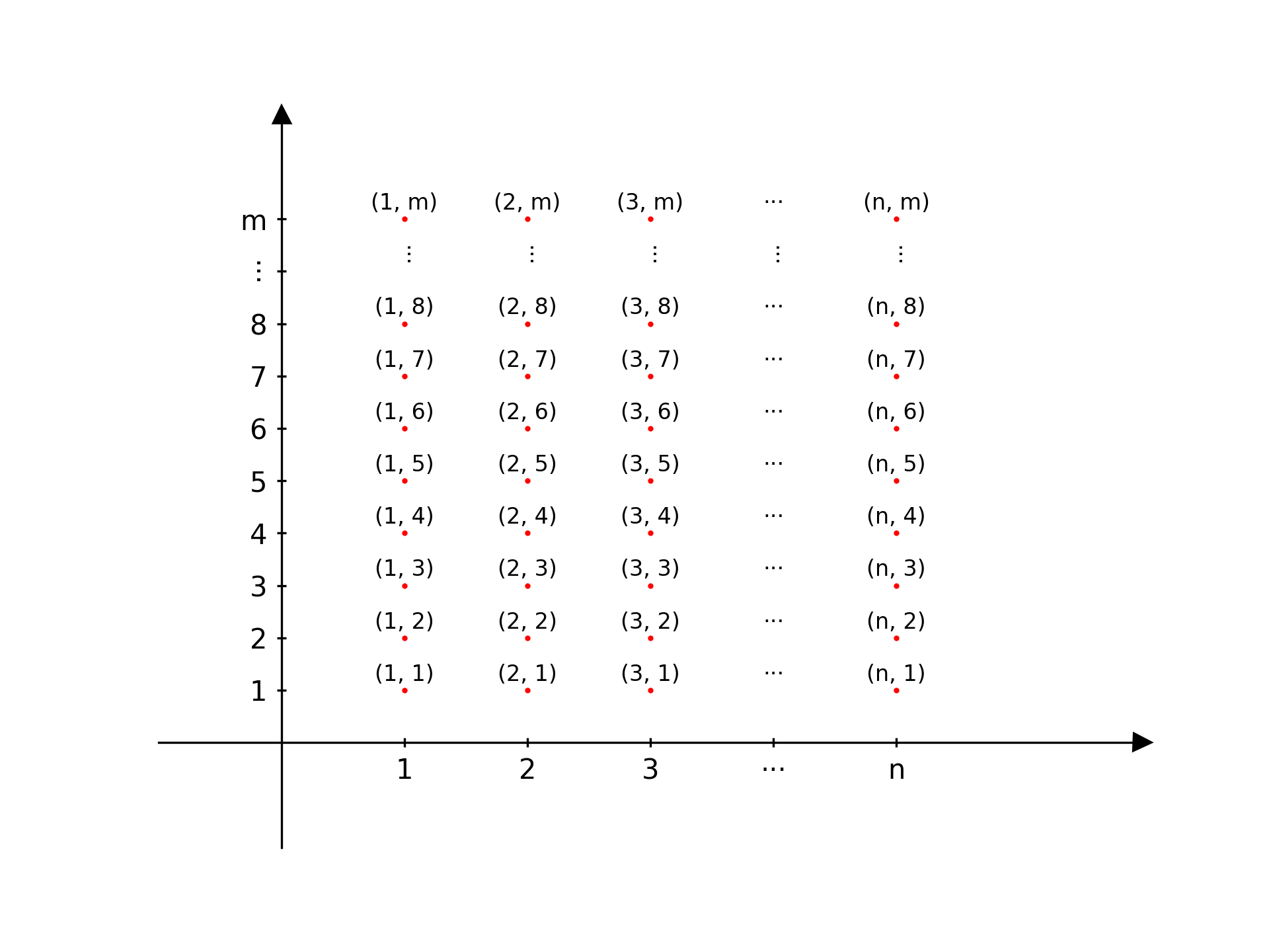
创建一张网格点图以更好地理解 numpy.meshgrid() 函数。
若第一个参数的维度为(n,),第二个参数的维度为(m,),那么由函数 X, Y = numpy.meshgrid(x, y) 返回的两个矩阵 X, Y 表示的网格点如下:
其中,返回的第一个矩阵包含所有网格点在X轴上的位置信息,第二个矩阵包含的是在Y轴上的信息。仅当两个矩阵在一起时才能清楚表达每个数据点在笛卡尔坐标系上的位置。
import numpy
from matplotlib import pyplot


x1_ax_contour = numpy.linspace(1, 5, 5)
x2_ax_contour = numpy.linspace(1, 10, 10)
xx, yy = numpy.meshgrid(x1_ax_contour, x2_ax_contour)
# m为x2的长度,意味m行。n为x1的长度,意味n列。
m, n = xx.shape
fig, ax = pyplot.subplots()
# 创建一个m行n列的空列表装m×n个text object
texts_array = numpy.array([[None for _ in range(n)] for _ in range(m)])
for i in range(m):
    for j in range(n):
        texts_array[i][j] = ax.text(x=xx[i][j], y=yy[i][j]+0.3, s=f'({xx[i][j]:.0f}, {yy[i][j]:.0f})', ha='center', va='center', fontsize=8)
# 将x=4与y=9的所有坐标对的标记改为省略符号,除最外围的坐标对
for text in texts_array[:, 3]:
    text.set(text='···')
for text in texts_array[8, :]:
    text.set(text='···', rotation=-90)
# 修改最外围坐标对,除开包含省略号的行列。如果是python list则使用.pop()来移除包含省略号的行列。
for text in numpy.delete(texts_array[9, :], 3):
    origin_text = text.get_text()
    origin_x = origin_text.split(',')[0][1]
    text.set_text(f'({origin_x}, m)')
for text in numpy.delete(texts_array[:, 4], 8):
    origin_text = text.get_text()
    origin_y = origin_text.split(',')[1][1]
    text.set_text(f'(n, {origin_y})')
ax.set_xlim(-1, 7)
ax.set_ylim(-2, 12)
# 将左边框和右边框的位置分别移动到x=0, y=0的位置
ax.spines["left"].set_position(("data", 0))
ax.spines["bottom"].set_position(("data", 0))
# 隐藏上边框和右边框
ax.spines["top"].set_visible(False)
ax.spines["right"].set_visible(False)
# 给x, y轴加上箭头
ax.plot(1, 0, ">k", transform=ax.get_yaxis_transform(), clip_on=False)
ax.plot(0, 1, "^k", transform=ax.get_xaxis_transform(), clip_on=False)
# 设置tick位置为卡在坐标轴中间
ax.tick_params(axis='both', direction='inout')
# 给x\y_ticks设置省略号
x_ticks_list = [f'{x:.0f}' if x != 4 else '···' for x in x1_ax_contour]
y_ticks_list = [f'{x:.0f}' if x != 9 else '···' for x in x2_ax_contour]
# 将最后一个元素更改为m, n
x_ticks_list[-1] = 'n'
y_ticks_list[-1] = 'm'
ax.set_xticks(x1_ax_contour, x_ticks_list)
ax.set_yticks(x2_ax_contour, y_ticks_list)
# 为y轴上的省略号设置旋转角度
y_ticks = ax.get_yticklabels()
y_ticks[8].set_rotation(-90)
# 把点展示出来,除了省略号的点
ax.scatter(x=numpy.delete(numpy.delete(xx, 3, axis=1), 8, axis=0), y=numpy.delete(numpy.delete(yy, 3, axis=1), 8, axis=0), s=1, c='red')
# pyplot.show()
pyplot.savefig('figure.png', transparent=True, dpi=300)

# 绘制logistic regression的决策边界
利用 .contour() 函数实现决策边界的绘制,该函数旨在生成给定数值的等高线。而作为决策边界,该给定数值应设定为0.5,因为大于等于0.5则判断为正例,否则判定为负例。
本例子中原数据仅包含两个特征,通过特征映射的方式生成维度更高的特征。而使用 numpy.linspace() 函数生成的两个数组好比原数据的两个特征值,在使用学习得到的参数预测优势比之前需要再次特征映射。
def plot_decision_boundary(w_db, b_db, ax):
    # 画等高线
    x1_ax_contour = numpy.linspace(-1, 1.5, 100)
    x2_ax_contour = numpy.linspace(-1, 1.5, 100)
    values_contour = numpy.zeros((len(x1_ax_contour), len(x2_ax_contour)))
    for i in range(len(x1_ax_contour)):
        for j in range(len(x2_ax_contour)):
            values_contour[i][j] = sigmoid(numpy.dot(map_feature(numpy.array([x1_ax_contour[i], x2_ax_contour[j]]).reshape((1, 2))), w_db) + b_db)
ax.contour(x1_ax_contour, x2_ax_contour, values_contour.T, levels=[0.5], colors='red')# 绘制决策树不纯度计算函数
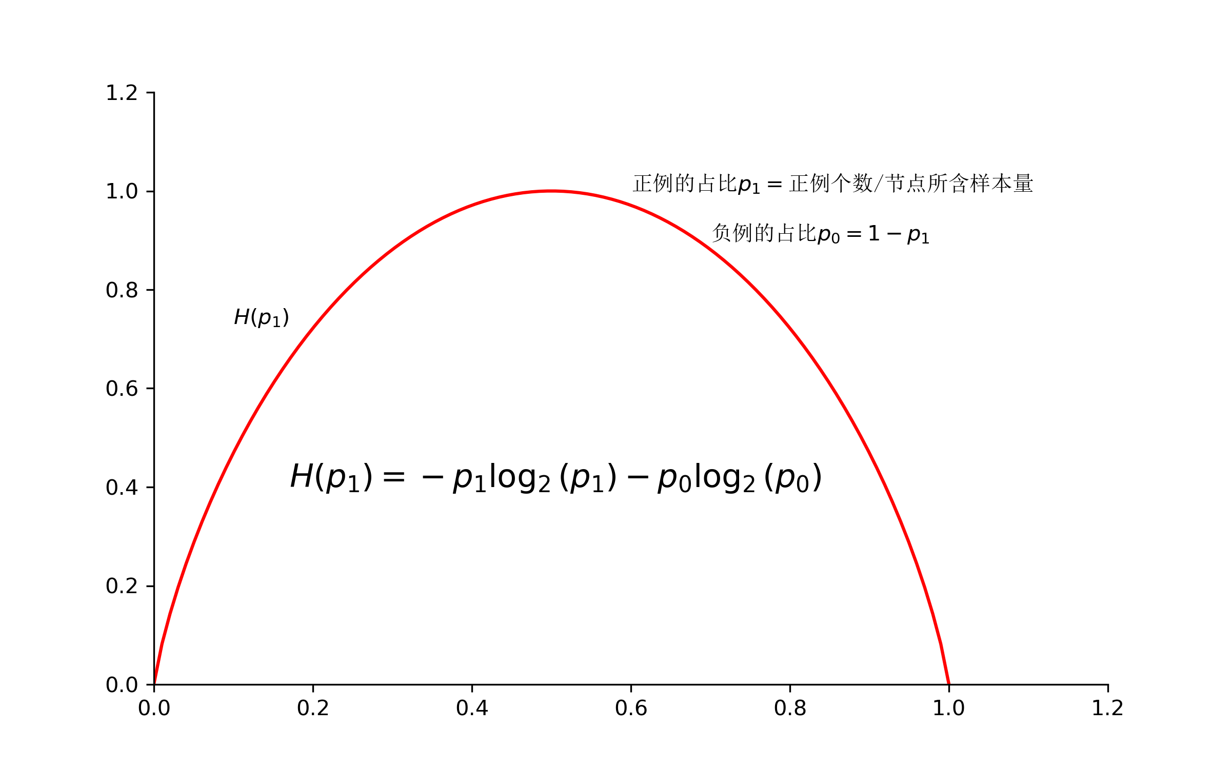
第一次在 matplotlib 中使用公式+中文,有了一些新的理解。在 $ 内等号之后的中文会乱码,尽管设置了中文字体。因此应使用 $ 结束公式后再输入中文。此外,为标题设置中文时尽量不更改全局字体,而是使用 fontname 参数为局部设置中文字体。
import numpy
from matplotlib import pyplot


# 定义数据
p_1_array = numpy.linspace(0.0001, 0.9999, 100)
y_array = -p_1_array * numpy.log2(p_1_array) - (1-p_1_array) * numpy.log2(1-p_1_array)
# 实例化一个图幅与一个坐标系
fig, ax = pyplot.subplots(figsize=(8, 5), dpi=300)
# 绘制函数曲线
ax.plot(p_1_array, y_array, color='red')
# 设置坐标轴区间
ax.set_xlim(0, 1.2)
ax.set_ylim(0, 1.2)
# 设置坐标轴样式,具体而言:隐藏右框与顶部框线
ax.spines.top.set_visible(False)
ax.spines.right.set_visible(False)
# 打印数学公式
ax.text(0.6, 1, '正例的占比$p_1=$正例个数/节点所含样本量', fontname='SimSun')
ax.text(0.7, 0.9, '负例的占比$p_0=1-p_1$', fontname='SimSun')
ax.text(0.2, 0.4, '$H(p_1)=-p_1\log_2(p_1)-p_0\log_2(p_0)$')
ax.text(0.1, 0.73, '$H(p_1)$')
# 展示
pyplot.show()

# 在原有ticks基础上增加额外ticks
并为额外部分设置不同颜色,或隐藏label。然后统一所有ticks的格式。
方法 .get_yticks() 返回的是 numpy.ndarray ,所以才需要将它转为自带的list。
ax.set_yticks(list(ax.get_yticks()) + [new_tick_1, new_tick_2])

# 设置格式
ax.set_yticks(ax.get_yticks(), [f'{i:.3f}' for i in ax.get_yticks()])

# 设置颜色
ax.get_yticklabels()[list(ax.get_yticks()).index(new_tick_1)].set_color('red')

# 隐藏数字label,这里的label是text.Text(),适用于其下所有方法
ax.get_yticklabels()[list(ax_in.get_yticks()).index(new_tick_1)].set_visible(False)
# 画一条用于指示数据的连结坐标轴底端的垂线
ax.set_ylim(ax.get_ylim()[0], ax.get_ylim()[1])
ax.plot([x_arr[0], x_arr[0]], [ax.get_ylim()[0], data[0]], 'r--', lw=1.3)
# 为subplots画连接线
from matplotlib import patches


zoom_rect = patches.Rectangle((0.995, 0.403), 0.21, 0.0078, fill=False, color='#5E6C82', linewidth=1, linestyle='--', lw=.5)
ax[1].add_artist(patches.ConnectionPatch(xyA=(0, 0), coordsA=ax[1].transAxes, xyB=(zoom_rect.get_x()+zoom_rect.get_width(), zoom_rect.get_y()), coordsB=ax[0].transData, color='green'))
# 线性回归的置信区间
需要使用 statsmodels 库来计算每个预测变量的置信区间:
import statsmodels.api as sm

# x_list是自变量
sm_X = sm.add_constant(x_list)
sm_ols_model = sm.OLS(Y, sm_X)
sm_est = sm_ols_model.fit()
sm_pred = sm_est.get_prediction(sm_X)
sm_pred_conf_int = sm_pred.conf_int()  # 返回的是list,list中元素为每个预测值置信区间的最大值和最小值
axes[0].fill_between(x_list.flatten(), sm_pred_conf_int[:, 0], sm_pred_conf_int[:, 1], alpha=.2, fc='red')
需要注意的是, statsmodels 在拟合模型之前需要手动添加截距项 .add_constant() 。
# 好看的Polar图
记录一下。
import matplotlib.pyplot as plt
import numpy as np

color_dict = {"Denmark": "#A54836", "Norway": "#2B314D", "Sweden": "#5375D4"}
countries = color_dict.keys()
values = [10, 8, 15]

fig, ax = plt.subplots(subplot_kw={"projection": "polar"}, facecolor="#FFFFFF")

for i, (c, v) in enumerate(zip(countries, values)):
    angle_range = np.linspace(0, v*10)
    r = np.full(len(angle_range), i + 1)  # identical radius values to draw an arc
    # plot a thick arc with the rounded cap style
    ax.plot([np.deg2rad(a) for a in angle_range],
            r,
            linewidth=20,
            solid_capstyle="round",
            color=color_dict[c])

# increase the r limit, making a bit more space to show thick arcs correctly
ax.set_rmax(len(countries) + 1)

# place custom ticks and labels
ax.set_rticks(range(1, len(countries) + 1))
ax.set_yticklabels(countries)

ax.set_theta_zero_location("N")
ax.set_theta_direction(-1)
ax.set_rorigin(-1)
ax.set_thetamax(180)

plt.show()
# LATEX数学公式
在图中使用斜体:
# 斜体
ax.set_xlabel('Set a $\it{tilted xlabel}$ right here')
当在公式中表示变量时使用斜体,表示其他意思时使用值立体:
# 输出时ab中间有空格
ax.set_xlabel(r'$\text {a b}$')
# 输出时ab中间没空格
ax.set_xlabel(r'$\rm {a b}$')
# 输出时ab中间没空格
ax.set_xlabel(r'$\mathrm{a b}$')
在图中使用下标:
ax.text(0.6, 1, '正例的占比$p_1=$正例个数/节点所含样本量', fontname='SimSun')在\(\text{Matplotlib}\)里使用原生\(\text{L$_{A}$T$^{E}$X}\)
有时不得不使用原生\(\text{L$_{A}$T$^{E}$X}\),以下是使用范式和注意事项。
安装\(\text{L$_{A}$T$^{E}$X}\)
\(\text{Windows}\)操作系统在官网下载安装\(\text{MiKTeX}\),而\(\text{MacOS}\)用户则推荐使用 homebrew 进行安装,方便管理、更新和卸载:
brew install mactex-no-gui
brew install ghostscript
\(\text{Python}\)里的使用范式
最好在文档开头设置好\(\text{L$_{A}$T$^{E}$X}\)参数:
from matplotlib import pyplot

pyplot.rcParams.update({
    "text.usetex": True,
    "font.family": "sans-serif",
    "font.sans-serif": ["Times New Roman"],
    "text.latex.preamble": r"""
        \usepackage{xcolor}
        \usepackage{amsmath}
    """
})
在\(\text{Matplotlib}\)原生的\(\text{L$_{A}$T$^{E}$X}\)中,数学公式依旧放在 $…$ 内:
pyplot.text(0.5, 0.5, r'\textcolor{green}{Green text$\alpha+\beta$}')此外,如果出现诸如颜色不能正确显示的问题,可以先输出\(\text{.eps}\)文件,再通过终端\(\text{epspdf}\)转换成正确的\(\text{pdf}\):
pyplot.savefig('test.eps')
# 然后进入终端
epspdf ./test.ps
需要注意的是,不要输出\(\text{.ps}\)文件,它会自动将\(figsize\)裁减到\(\text{A4}\)纸大小,丢弃区域外的要素。
如果提示以下错误:
latex was not able to process the following string:
b'\\n\\\\begin{figure}\\n
那么注意是否有 % 等符号未转译 \% 。
还原字体
当全局指定\(\text{usetex=True}\)时,\(\text{L$_{A}$T$^{E}$X}\)的默认字体\(\text{}\)将覆写其它所有字体。因此,如仅需在个别地方使用原生\(\text{L$_{A}$T$^{E}$X}\),建议在这些地方手动指定\(\text{usetex=True}\):
pyplot.rcParams.update({
    "font.family": "sans-serif",
    "font.sans-serif": ["Times New Roman"],
    "text.latex.preamble": r"""
        \usepackage{xcolor}
    """
})
ax[1].text(xi, 1.02, s=rf'\textcolor{red}{1}', ha='left', va='bottom', fontsize=11, weight='bold', rotation=45, usetex=True)
此外,也可以在每一处不希望改变字体的元素中指定\(\text{usetex=False}\)。
# 数据可视化
# 隐藏与\(X\)和\(Y\)轴有关的所有信息
不用再设置\(\text{spines}\)和\(\text{ticks}\)了。
ax.axis('off')# 仅输出图片并隐藏坐标轴和四周的白色背景
img = torchvision.io.read_image(f'{img_dir}{file_name}', mode=torchvision.io.image.ImageReadMode.RGB)
w, h = matplotlib.figure.figaspect(img.shape[1] / img.shape[2])
fig, ax = pyplot.subplots(figsize=(w, h))
ax.imshow(img.permute(1, 2, 0))
ax.axis('off')
pyplot.tight_layout(pad=0)
pyplot.savefig('testsave.jpg', dpi=600)
# 上下左右颠倒子图
axes[1].invert_yaxis()
axes[1].invert_xaxis()
# 隐藏tick
axes[1].yaxis.get_major_ticks()[0].set_visible(False)